Michel Gambin – Quelques communications récentes
Conférence Coulomb
Paris, 4 juin 2010
Comité Français de Mécanique des Sols et de Géotechnique (CFMS)
Eoliennes et module d’Young
Au cours de la réunion technique du CFMS sur les éoliennes j'avais promis de faire parvenir au CFMS une Note Technique sur le "Module d'Young" : la voici.
Je souhaiterais que cette note reçoive une grande diffusion au sein du CFMS, car comme le dit Olivier Combarieu : " L'erreur provient du fait qu'on applique aux sols des modèles de calcul par élément finis développés pour des matériaux pour lesquels la théorie de l'élasticité est tout à fait acceptable " .Il ajoute : " Maintenant, en France, on ne maîtrise plus la situation et je crois que cela mériterait au niveau national une réflexion d'envergure. Je suis très surpris de voir que, au sein de certains Projets Nationaux, dans les travaux présentés par des participants, les sols compressibles sont caractérisés par un module d'Young et un coefficient de Poisson ! "
Ne devrions nous pas ouvrir un "libre débat" sur le sujet, en lançant une "tribune" sur le site Internet du CFMS (une nouvelle rubrique apparaîtrait dans la liste de gauche - "roster" en américain - de la page d'accueil de notre site) qui serait amorcée par ce texte et un commentaire d'Olivier Combarieu ?
Au cours de la réunion technique du CFMS du 20 octobre 2009 sur les éoliennes, plusieurs conférenciers ont insisté sur le rôle du « module d’Young » dans le projet de fondation des éoliennes pour respecter les règles industrielles des fournisseurs des appareils.
Or si je me réfère à la communication exhaustive d’Olivier Combarieu sur « L’usage des modules de déformation en géotechnique » parue dans la Revue Française de Géotechnique N° 114 du 1er trimestre 2006, je n’y voit jamais apparaître l’expression « module d’Young » !
C’est que, malgré les quelques références au « module d’Young » dans l’Eurocode 7i, le module d’Young n’a pas de sens intrinsèque !
Reprenons la figure 5.6 du cours de G. Philipponnat & B. Hubert sur « Fondations et ouvrages en terre » (Eyrolles, 2001, 2ème tirage de 2002ii), l’ouvrage en français le plus récent sur notre sujet. Cette figure exprime la relation entre σ, la contrainte principale majeure appliquée à un échantillon cylindrique soumis à un essai triaxial eεt, la déformation relative (dh/h) qui en résulte.
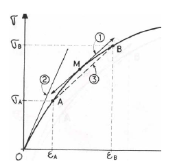
Sur cette figure on met en évidence qu’il existe sur un seul échantillon une infinité de « modules de déformation » :
- des modules tangents, pente des droites de type (1), variables en tout point de la courbe
- un module à l’origine Eo , pente de la droite (2)
- des modules sécants entre les 2 points A & B, pente des droites de type (3)
- et des modules entre l’origine O des coordonnées et tous les points A sur la courbe.
Quand l’abscisse du point A est la moitié de la contrainte de rupture, on a le fameux E50 des programmes PLAXIS.
Même dans l’hypothèse où le sol se comporterait comme un matériau parfaitement élastique, linéaire et donc réversible, la grandeur "module de déformation" n'est pas une grandeur évidente, sa définition n'étant connue qu'à l'échelle d'un élément cubique infinitésimal
εx = 1/E [σx - ν (σy + σz)]
et les 2 autres formules associées donnant εy et εz.
Le passage à un sol de fondation soumis à un chargement est toujours risqué, en raison :
- de la variabilité des caractéristiques mécaniques du sol étudié,
- d’une certaine méconnaissance de la répartition des contraintes dans le sol
- de la non linéarité des déformations en fonction des contraintes et
- du phénomène de dilatance.
Le dernier point a son importance, car les 3 formules données ci-dessus n’entraînent qu’une seule propriété : la déformation des solides n’est provoquée que par les seules contraintes normales.
Or, dans les sols, c’est le cisaillement qui est à l’origine d’une grande partie des tassements.
La première communication sur ce sujet est celle de Roscoe, K.H., Schofield, A.N. et Wroth,
C.P. : On the Yielding of Soils, dans Géotechnique Volume 8, Issue No.1, p.22-53, 1958.
C’est D. J. Henkel (Géotechnique, Vol. 9, No.3 p.119-135, 1959) qui avait fait la synthèse sur la possibilité d’exprimer les déformations supplémentaires (dilatance ou contractance) à partir du cisaillement octaédrique τoct (toujours sur un élément infinitésimal), dont le carré vaut théoriquement
(1/9) [(σ1 – σ2 )2 + (σ2 – σ3 )2 + (σ3 – σ1 )2 ]
et où les σi sont les contraintes principales appliquées au petit cubeiii.
Ainsi l'étude analytique fine est-elle stérile et seule l'étude synthétique globale apporte une réponse pragmatique au géotechnicien.
Revenons donc maintenant au concret: quand on me demande quel serait le module traditionnel du sol, je dis simplement
« Observez le tassement s de la fondation ou calculez son tassement par une méthode sûre et, par une analyse en retour, déduisez EY de la formule du mathématicien Boussinesq pour la même fondation
s = Cf [(1- ν2)/ EY ] B q
où s a été calculé ou observé, et Cf , B et q sont connus ».
J’avais été satisfait de constater qu’Olivier Combarieu utilise la même démarche dans son article dans la RFG N°114 de novembre 2006, p.22, avec une variante : au lieu de la formule de Boussinesq, il prend la formule présentée par Giroud pour ses tables de 1972-73, laquelle intègre le facteur de Steinbrenner.
Je rappelle que c’est de cette façon que le « coefficient de raideur » ou « module de réaction » du sol (supposé constant pour une largeur du semelle donnée) est calculé quand on traite des déformations des poutres sur sol élastique, à partir des résultats des essais pressiométriques (Apagéo, Brochure dite « D 60 », § 4.9, p. 53-54, mise à jour de 1998 pour être en conformité avec l’Eurocode 7).
Il nous reste encore deux « modules » à étudier,
- le « module oedométrique » qui est une invention française, car pour les promoteurs de l’essai oedométrique, le seul paramètre relativement constant dans les plages de pression des ouvrages de génie civil, c’est l’indice de compression Cc mesuré sur les graphiques de l’essais en coordonnées semi-logarithmiques, et
- le module pressiométrique Ménard EM dont l’utilisation pour l’estimation des tassements a été étudié de 1960 à 1965.
En ce qui concerne le « module oedométriqueiv » ou mieux Cc, son utilisation (dans une formule logarithmique impliquant Cc) pour estimer le tassement de semelles de dimensions variables, donc sujettes à des tassements différentiels non négligeables, est limitée aux couches peu épaisses, et drainées sur au moins une face, à moins d’opter pour une fondation profonde.
En ce qui concerne le « module pressiométrique »v, son utilisation fait intervenir plus de paramètres que les formules de Boussinesq ou de Giroudvi, car la formule de l’estimation du tassement de Ménard intègre les recherches expérimentales des Professeurs Terzaghi et Peck avec lesquels il avait travaillé 1 an et demi en 1955 - 1957. C’est l’ensemble des phénomènes pris en compte par ces recherches qui sont exprimés par le coefficient de structure α, et donnent à sa formule une grande fiabilité, à condition que les essais pressiométriques soient réalisés correctement !
Je conseille toujours de revenir aux sources et de relire l'article de Ménard et Rousseau dans Sols-Soils N°1 (juin 1962). Avant de le lire, on doit se rappeler que Louis avait déjà écrit sa communication pour le Congrès International de Paris (1961) où il expose ses vues sur le module de déformation E, une fonction décroissante de l'intensité de la contrainte. Et quand on lit ce premier numéro de Sols-Soils, on est étonné que chaque mot compte, chaque figure est novatrice ... et qu’on dénombre au moins 4 modules différents :
- E, le module pressiométrique Ménard, ou module « pseudo-élastique »
- Eε , le module de micro-déformations , le seul véritablement « élastique »
- Ea , le module « cyclique » (appelé, à tort, module alterné dans la communication) et
- E+, un module très voisin du « module oedométrique ».
Foin des corrélations hasardeuses : si vous voulez obtenir un « module d’Young » équivalent pour votre fondation, utilisez l’une des 2 méthodes pratiques données ci-dessus. Mais n’oubliez pas que vous serez amenés à travailler par approximations successives, puisque la largeur de la fondation est un paramètre des formules, d’autant plus que d’après les règles de construction des industriels fournissant le matériel, vous risquez de devoir modifier votre projet selon que « EY» est inférieur à 15 MPa, compris entre 15 et 50 MPa ou supérieur à 50 MPa.
Peut-on terminer en citant mon Professeur Jean Kérisel qui écrivait dans son Traité de mécanique des sols publié en 1956 avec le Prof A. Caquot (Gauthiers-Villars éditeur), p.129 : « Aussi bien pour les sables que pour les argiles, il n’y a pas de module d’Young invariant ».
i Dans l’Eurocode 7-1, traduit en français dans la norme AFNOR NF EN 1997-1 de juin 2005, on lit au
§ 3.3 Evaluation des paramètres géotechniques, que
- pour le sol on mesure une raideur du sol (§ 3.3.7). Ce terme de « raideur » traduit le mot anglais « stiffness » de sens beaucoup plus général puisqu’il signifie l’« élasticité » en géotechnique.
- et pour la qualité et propriété des roches (§3.3.8), très exactement au § 3.3.8.2 « Résistance en compression simple et en déformabilité des matériaux rocheux » on recommande de préciser l’influence de la méthode de détermination du module d’Young et le(s) niveau(x) de la contrainte axiale pour le(s)quel(s) il est(sont) déterminé(s)
Enfin, dans l’Annexe F, qui est seulement « informative », et relative aux « Exemples de méthodes d’évaluation du tassement », après une méthode en « contraintes et déformations » donnée en F.1, qui nécessite l’emploi de logiciels, il est proposé une « Méthode élastique ajustée » en F.2 où le tassement s est donné par
s = p b f /Em
dans laquelle : Em est le module d’élasticité
et f un coefficient de tassement qui, en sus de la forme et des dimensions de la surface de la fondation, inclut « la variation de la raideur avec la profondeur », l’épaisseur de la couche compressible, le coefficient de Poisson et la répartition de la pression de contact.
Quatre garde-fous sont donnés au sujet de cette méthode, dont les 2 suivants :
- « quand on ne connaît pas de valeurs de tassements utilisables », la « valeur de calcul » du module d’Young drainé Em peut être estimée à partir de résultats d’essais in situ ou au laboratoire.
- il convient d’utiliser cette méthode seulement « quand la relation contrainte-tassement du sol peut être supposée linéaire », - ce qui n’est généralement pas le cas -.
On remarquera enfin que dans la norme dite « d’application nationale », NF EN 1997-1/NA (ou P94 251-1/NA) de juin 2006, il n’est pas fait mention de “module dYoung”.
ii Car le premier tirage avait une coquille en page 192. On y lisait Eoed = α . EM, au lieu de
Eoed =EM /α
iii On trouvait une bonne présentation sur ce sujet dans le manuel "Principles of Soil Mechanics" par Ron Scott, 1963 (chapitre 6). Il y a sans doute mieux maintenant.
iv Calculé pour trois contraintes principales en compression de valeurs très voisines, Eoed peut s ‘exprimer en fonction de E (essai triaxial drainé) dans un matériau qui serait strictement élastique par
E = Eoed [(1 + ν)(1 - 2ν) / (1 – ν)]
soit pour un coefficient de Poisson (en conditions drainées) ν = 0,3 : E = 0,74 Eoed .
v Le module pressiométrique EM est calculé à partir de l’expansion radiale Δr de la paroi d’un forage de rayon r sous l’effet d’une pression p croissant par paliers dans la phase « pseudo-élastique » de réponse du sol à l’aide des 2 formules ci-dessous
Δr/r = [1/2G] Δp
EM = 2,66 G
Cette deuxième formule n’exprimant qu’une application numérique de la formule générale E = 2(1 + ν) G, dans laquelle le coefficient de Poisson a une valeur conventionnelle de 0,33. La phase pseudo élastique durant l’essai pressiométrique correspondant à des déformations relatives du sol à la paroi du forage de l’ordre de 10-3 à 10-2, la valeur de EM est, quant à elle, bien entendu, unique. Réalité qui peut conduire à confusion, en raison de la multiplicité des autres « modules » précédemment définis.
vi Le facteur de Steinbrenner fait également partie de la fonction λd (L/B).
Reminiscences – II
Frank: Dear Mike, we thought that as your education was completed more than 50 years ago in several countries, France, UK and USA, and that you have worked all over the world, you could bring an unusual perspective to the Geotechnical community. This interview will be a stone in the arch of your Golden Jubilee.
Mike: Yes, I did receive my education from some famous Engineers. Jean Kérisel who was President of the ISSMFE from 1973-1977 was my teacher at ENPC in Paris (1952-1953). Secondly I studied with Arthur Casagrande and Karl Terzaghi at the Graduate School of Arts and Sciences Harvard University where I was the recipient of the Augustus Clifford Tower Fellowship for the year 1954-1955. I was also granted a partial enrollment at MIT where I received additional lectures from two distinguished teachers, namely Prof. D. W. Taylor in Soil Mechanics and T. W. Lamb on clay mineralogy. I was also trained in the UK with the contracting firm McAlpine in 1953 working on the foundations of Broms Hall II Power Station near Birmingham and, at Easter 1954, I visited Egypt, landing at Alexandria from a Lloyd-Triestino regular steamer to visit Aswan Dam III under construction some years before the High Dam started. Nowadays young students get scholarships to foreign countries very easily, and fly everywhere. In 1954, I reached New York City on SS Ile-de-France and the trip back to my home country in 1955 was on the brand new MS United-States.
Casagrande and Terzaghi I still remember well, both were great men. Casagrande was a marvellous teacher: every student easily understood his courses and his English was good. He would often refer to the experiences gained from his German colleagues before WWII and to the theories of Prandtl, Hvorslev and others. His course on pore pressures and sand liquefaction was unforgettable.
Karl Terzaghi was teaching Engineering Geology which included site investigation. He was presenting his own expertise from dam sites all across the world. He also talked about SPT and CPT and explained how the cone penetration test results could be improved by various unusual techniques, such as slurry flushed upward above the tip.
His English was awful and I had to give my notes to my classmates for them to get a better understanding. What surprised me most was the following advice: “Do not buy my book on Theoretical Soil Mechanics; what you really need to know is in my second book written with Prof. Peck”. He would also say “These days, I spend more time and effort preventing design engineers using my theories wrongly, especially that on the consolidation of thin normally consolidated clay layers, than I do on new research work”. I never asked Harry Seed (class of 1947-1948) or Jim Mitchell (class of 1952-1953) if they remembered he had said so in years before. These statements, however, are supported by a personal communication from Prof. Peck to the authors of a Technical Note in Volume XXXII of “Géotechnique” (December 1982): “[Terzaghi] was not, as he was the first to admit, a theorist beyond the extent that seemed necessary to understand the behaviour of earth material. (…) It might well be that, in Vienna, when Frölich and Terzaghi were cooperating on their book, Terzaghi was more than happy to let Frölich elaborate on and manipulate the theory as much as he desired”.
Frank: You then spent 30 months in the French Army for your National Service, being, during the last year, a Lieutenant in the Corps of Engineers, partially acting as an instructor at the French Army School of Engineers in Angers. What then ?
Mike: I had been contacted by Prof. Kérisel to work with him at his newly opened Consulting Firm Simecsol in Paris, but the shareholders of the recently incorporated company Les Pressiomètres Louis Ménard convinced me to join my younger ENPC classmate Louis Ménard who had yet to perform his military service. In this way my professional life started and I am still in the same business, more than 50 years later.
After his initial military training period, Louis got a good position with my help at the Army Fortification and Building Design Office in Paris for the rest of his 30 months obligations and we could meet every day to run the company.
I knew about the patent that Louis had been granted for a new instrument to test the soil by borehole expansion, his pressuremeter, but I had never seen the equipment. As a man of vision, in the draft of the patent he had said: “the equipment is used to characterize the ground by a bearing factor” (see the facsimile of the handwritten draft in ISP5, Volume 2, p.55, lines 5 & 6 of the introduction). This is what he demonstrated as early as 1962.
I found him drilling holes – 60 mm in diameter - with a hand auger up to 10 metres depth to insert his rubber clad pressuremeter probe, and that by hand too. We soon started developing a drilling technique involving mud circulation to create a non-caving cavity to perform pressuremeter tests (PMT) in loose sandy soils below water table. We tested the technique at various locations using portable hand pumps as for plant treatment in gardens. We also tested larger probes in larger holes but we then got too many bursts. After that, we started using conventional drill rigs with drag bits and also compressed air drifters since our aim was not to retrieve core samples before testing but to get a borehole wall as intact as possible in all types of ground. I had to educate young farmers to become drillers and pressuremeter operators. The fact that I had enlisted as a private in the Army helped me a lot. I had learnt how to control men and equipment. We had more and more clients for site investigations with PMTs, mostly brought by the same shareholders, since they had good contacts with the Paris Ministry of Public Works, with architects and with contractors.
At the same time as we improved the testing techniques, we had to develop the derivation of the parameters, the E-modulus, derived from a G-modulus and now called EM and the limit pressure pLM. Then the theory behind these parameters had to be refined, and the method of using these results in foundation design to be worked out. Louis Ménard’s main concern was to develop a foundation design based on allowable differential settlement between footings by following the advice of Prof. Terzaghi (as in Article 54 of his book with Prof. Peck) and using the results of our tests.
For this reason the first papers were written on “the E-modulus as a function of the stress or strain level” (Paris 5th ICSMFE, 1961) and “Settlements, New Trends” (Sols-Soils, 1962). They incorporated the decline (the American Geotechnical Engineers would say: degradation) of EM as a function of strain level (with the first diagram of that sort in the geotechnical literature) and the importance of the shear effect on the settlement of footings on relatively homogeneous soils. Unfortunately, these papers were written in French and were barely noticed in the Anglo-Saxon world. Still, it was the start of a new vision of soil “elasticity”. We undertook a large number of full scale vertical bearing capacity and settlement tests on shallow footings and piles in the basement of our newly built office building at our Centre d’Etudes Géotechniques near Paris, using its huge specially designed beams to provide the required reaction. The whole building would hiss each time the ultimate load was reached. Then papers on “bearing capacity at failure from PMT” were published (Montreal 6th ICSMFE, 1965) where the replacement was proposed of the Terzaghi bearing capacity equation by one involving (1) the soil reaction to borehole expansion as defined by pLM and (2) a “relative depth” concept. A paper on the “Settlement of piles” (Sols-Soils No.7) followed based on a totally new concept far from that of Gorbunov- Posadov.
Geotechnical Engineering was greatly changed. Not only were clients flocking into our offices but Engineers from all over the world came to listen to us. Prof. J. Schmertmann probably wrote his paper on settlement prediction from CPT results after his meeting with Louis in the late 1960s. Nevertheless, old habits remained and only a few adopted our views, which were before their time. At this time we submitted geotechnical reports based on the results of PMTs to design most of the underpasses and overpasses of the well-known Boulevard Périphérique of Paris, the riverside Voie Express Georges Pompidou, and the A1, A7, A10, A11, A13 motorways radiating from Paris. Our partners did the same in the other regions of France. Among them, the network of the LPC (our FHWA), was very active. They undertook research work, either on theoretical points or on more load tests on prototype foundations. You will remember, Roger, your PhD work at that time on modelling pile settlements and its further developments.
Frank: Your team was one of the first to undertake full scale horizontal loading tests on piles and on sheet piles ?
Mike: Yes we were. After a first series of lateral loading tests on piles performed in the quicksands of Mont St. Michel Bay by Louis Ménard, a second series was undertaken at the Centre d’Etudes, and completed by tests in Japan by Dr. H. Mori. That was only a few years after Ken Roscoe had said “[at that time] Soil Mechanics theories did not contain any mention of displacement, except for vertical settlement. Presumably the designer was meant to assume that the foundation did not move until the soil failed and then the movements were catastrophic”. The research work on the application of the results of PMTs to the design of laterally loaded structures lasted until the late 1960s with several papers, among them “Lateral loading of short piers” and ”Lateral loading of flexible piles”. The “Design of Sheet Pile Walls” followed involving new computer programs developed by our team.
Frank: In the same time you became busy at sea ?
Mike: Yes, in the mid 1960s Insurance experts started to ask us to check the security of exploratory jack-up drilling barges at sea for the oil industry. The soil response to a pressuremeter test was very similar to the soil response under each jack-up barge spud leg when the whole barge is ballasted so long as each leg is forced down in turn to refusal. I remember that once we predicted a spud depth penetration below mud line, not knowing the platform was of a new design where the 4 legs are pushed together. Further, the barge was tugged to its location as the monsoon was starting. The soil liquefied simultaneously under all the spuds due to the effect of the ocean swell and the oil company had to return the barge to port, and wait for the next dry season.
For that sort of soil investigation, we developed a hydraulic vibro-hammer which could drive the PMT probe deep enough below the spud depth penetration and could easily work from any ship. We also used the pressuremeter for many other types of off-shore jobs: not only for oil production platforms in the Mediterranean Sea, the Arabian Gulf, or the South-East Asian Seas, but also for floatingstorage- and-offloading buoy anchors. The vertical forces on these piles and the tractive efforts on the anchors is up to ten times that which we find on land. Dimensions are according, i.e. piles of 2 metres and more in diameter. Soil liquefaction could occasionally occur. Off-shore Tunisia a pile designed for an embedment of 45 m sank in seconds to 100 m below mud line. In the Macassar Strait the owner followed our recommendation. He stopped driving piles at the recommended depth and without observing refusal. Next month, none of the piles would move when re-driven.
In 1969 I was also involved in the design of one of the first submarine off-shore oil reservoir in the Trucial States – now the United Arab Emirates. Not a single private automobile on land but one traffic light. To cross the creek, you had to whistle the ferryman. Then, we slept on the floating pontoon in portacabins. One night, a strong gale arose, the anchors and the electric generator failed and then no radio. We finished stranded along the Sir Bu Nu’air Island, a territory claimed by Iran… Next afternoon, a search boat found us.
Piers for bridges crossing straits can also raise problems. I remember arriving at the Messina Strait in 1969: “- Where is the platform ?”, “ – Oh, my gosh, it has disappeared !”. It was a monopod platform resting in 100 m of water and tied by 12 anchors. One failed and the monopod crashed to the sea bottom. We returned a few months later for PMTs up to 160 m depth under a 4 leg platform. The bridge is not yet constructed, but it is now designed for piers on land. I must say, each off-shore site investigation was a real adventure.
Frank: Coming back to land, what about Dynamic Compaction ?
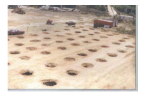
Mike: This is another series of patents of Louis Ménard’s, which might have been based on two Soviet processes, one to treat loess where you tamp the soil with a heavy pounder and the other to densify thick layers of granular fills below water level – as sea dikes – by using explosives. The second method had been tried during the construction of Franklin Dam in the USA in the 1930s but with no follow up. The secret was to have discrete tamping points on the ground surface and to tamp a defined number of blows at each spot. Prints can be more than 2 metres deep, the car gives the scale of the prints on the photograph. Densification is not just obtained by compression, but more by the shear effect, a point which is not always understood. Success came immediately because Louis checked the resulting improvement by using his pressuremeter. Had he not be able to, it would have taken years before international recognition. Dynamic compaction is mostly aimed at increasing the EM yielded by PMTs. Bearing capacity at failure can also be increased but generally at a lesser rate. CPT is not a suitable tool for that sort of quality control, since it only yields a failure parameter qc. Further, when the soil went through a liquefaction phase, liquefaction may re-appear and qc dramatically decrease during acceptance tests.
I designed many big jobs in France and around the world: the new air-strip at Nice on French Riviera, on crushed rock, the first phase of the new Changi Airport at Singapore on sand fill over marine clay, new ship-building yards in Sweden, Nigeria, Iran, etc. Also the soil treatment for large factories or warehouses in Sweden again, in Bangladesh, Indonesia, Korea, mainland China, etc. I was involved in the design and construction of the Chek Lap Kok airport of Hong-Kong, and various dams foundation in Mexico, Thailand, etc. I remember having to design a soil improvement scheme in South-East Asia based on a soil report submitted by a Western firm. Identification parameters were fine, except everyone forgot about quoting bulk density. The first time I visited the site I was horrified for it was pumice and we never could have achieved the expected EM. However, the owner was so satisfied that I worked for him as a consulting engineer on many other big projects.
Frank: What about your experience as a Managing Director overseas ?
Mike: In the mid-seventies I was in charge of Ménard Techniques Ltd, in Aylesbury, North-West of London and I designed several dynamic compaction jobs over old fills for new roads projects around London. I was helped by Malcolm Puller and Turlough Bamber. We had Joint Venture agreements with Cementation Piling and GKN who later bought up Keller. In the late seventies, especially after the untimely death of Louis Ménard, I managed Ménard Inc. in Pittsburgh, at that time the heart of soil improvement, with the head offices of Vibroflotation Inc. and Hayward-Baker Inc., which later was also bought by GKN-Keller. There, Techniques Louis Ménard Company had a joint venture with Elio D’Appolonia Inc. and we got much support from his son David. I undertook 3 jobs then, one in Santa Cruz south of San Francisco for the State of California, one east of Chicago along Lake Erie for a large tank farm and one in Baltimore, all based on the experience of a first job in Jacksonville, Florida. American Engineers did not waste time and started imitating us, initially for densification of old fills on FHWA projects. Now, several big American firms offer this method which has become public property.
Frank: Mike, I think that during all these years you always had extra-curricular activities ?
Mike: You are right, Roger. Already, at high school, I was editing a weekly newspaper Le Lycéen on mimeographed sheets and which included an editorial, detective stories, games, a movie chronicle, etc. Some years later I was involved in many student associations. This is how I was in the French delegation invited by Frei Universität Berlin in 1951 to counterbalance the gigantic World Peace Youth Meeting organized by the USSR in Berlin. There I was really impressed by the power of the USSR and decided to learn more about it. This is why I learned Russian during my military service, which helped me much later to win a court case for patent infringement as a defendant, since the patent method on which the plaintiff based his action was partially described in the Soviet Geotechnical Magazine the year before his patent application.
I was an active member of the UGE, the French Engineering Students Association, and I represented the UGE at the first meeting of the European Federation of Engineering Students in 1953 in Ghent. I rapidly became Vice-President of the Paris Division of the Mutuelle Nationale des Etudiants de France (MNEF) which was running the social security for students and later I became Secretary General at the national level of the MNEF.
I don’t know whether my involvement in the editing and publication of Sols-Soils magazine from 1962 to 1980 can be considered as extra-curricular or not. The 35 issues not only contained prominent papers either in French or in English on Geotechnical Engineering but also included abridged translations of papers published in German, Russian and even Japanese.
The same question occurs with my introducing an additional Working Group (No.5) to CEN TC341 to write the EN ISO Standards on Expansion Tests in Boreholes, which naturally includes the Ménard pressuremeter test.
During all my years of demanding professional activity from 1958 to 1992, I could not commit myself to participate in associations on a voluntary basis. We could simply entertain friends and clients in our flat overlooking the River Seine on the Isle Saint-Louis. Among many others, delegates of Japan, USSR and China would often visit me.
Frank: Now, what about your involvement within ISSMGE ?
Mike: As I said, my activities would not permit any large commitment to any type of Association or Learned Society. However, as early as 1987 I initiated a European Regional Technical Committee No.4 on Pressuremeters which produced a report for the European Conference held in Florence in 1991. This Committee became ISSMGE Technical Committee No. 27 (see the photo) which produced another report for the first International Conference on Site Characterisation in Atlanta (1998). TC 27 was merged with TC 16 which thus became devoted to all types of in situ testing. I was a member of TC 16 until 2001, and I remain a friend. From 1998 to 2002, I was Vice President of CFMS, the French Geotechnical Society and from 2001 to 2005 I was an appointed member of the ISSMGE Board.
Being a francophone Engineer, I thought it my duty to transfer our Geotechnical knowledge to our friends in Africa and to some other, more isolated places, I am thinking of Haïti for instance. So, with the help of the newly formed CFMS Committee for a Francophone Cooperation, which included academics and engineers from Belgium, Switzerland and Canada, we collected the addresses of francophone higher education establishments overseas. The first Francophone Geotechnical Libraries partially funded by ISSMGE were distributed during a first meeting held in Marrakech, Morocco, in September 1996. In the meantime I had started to translate the “ISSMFE News” and mail it. Then from December 1995 on, I edited, with the financial help of ISSMGE, a quarterly Lettre de la Géotechnique which is still in existence and now posted on the ISSMGE website. After that, I thought it necessary to set up an ISSMGE Member Society representing the French speaking African Geotechnical Engineers and Academics: the CTGA or Trans- national African Geotechnical Society which gathers those dwelling in the 20 African francophone countries - excluding the 3 North African ones who have their own Society. Finally, in 1998, with the help of my former college ENPC, and with you, Roger, I set up a yearly 3-week program of Continuing Education for African Engineers, held in Paris. Along the same line, I tried to bring francophone lecturers to the Annual General Meetings of the CTGA to help the development of sound geotechnical engineering in Africa.
Frank: And in conclusion ?
Mike: My task, I think, will last as long as my life. It is difficult for me to see that the message from Louis Ménard dating back to the early 1960s has not yet been accepted by the whole Geotechnical Community, although the number of instruments sold has now passed the 1000 mark. Sometimes, I hear “what is new with foundation design using PMT ?”. The answer is “The whole basis was set up in the 1960s and only refinements can be worked on”. A few books were devoted to the pressuremeter and its use in design, but none of them really stressed the basis on which Louis Ménard developed his 2 simple equations on soil displacement and soil failure under load based on PMT results. Even now, teachers and students are still much too happy to work on mathematical theories they enjoyed so much during their college years and forget about the reality of soil. Use of more and more effective computer software makes them think that soil behaviour is in the memory of their electronic devices. I was very puzzled when I saw the cover of an ASCE magazine on student theses showing a young student in front of a computer key-board !
Last year I wrote a paper on the fallacy of the Terzaghi (or Frölich ?) equation for footing bearing capacity (ISC‘3). This was already implied in the Terzaghi and Peck book, page.420-422 (1948 edition). Since 1994, J.-L. Briaud has worked on this subject and has reached the same conclusion. This year or next year, health permitting, I shall write a paper on “Settlement and shear”. For the first International Conference on Education in Geotechnical Engineering, in 2000, I have written a paper on the history of defunct Soil Mechanics theories. I would like the theories of the first half of the 20th Century to be at least limited to their own region of application and, better, superseded by newer concepts in these days of sustainable development.
In the pursuit of a myth
1. INTRODUCTION
I am always surprised when I read : "All new procedures for foundation design using in situ tests results are shown to perform well and often better than more rigorous approaches based on lab tests” (undisclosed authors, 2001). Are these methods based on lab tests so “rigorous” indeed ? Don’t they exhibit some shortcomings ? It is what I shall investigate.
The reason for this belief of a rigorous nature granted to the academic approach of foundation design is certainly due to the way physics, and geotechnical engineering as well, are taught. Principles and theories are delivered by professors in a straightforward way since they have to be considered as the truth by the young students if they want to pass their exam.
But Geotechnical Engineering theories have their shortcomings, which are not always sufficiently pointed out and they may be replaced by other theories periodically. In another paper (Gambin & Magnan, 2000) I already exemplified the large variations some geotechnical theories underwent over the past 5 decades and how some of them were detracted from their original aim.
2. THE TERZAGHI BEARING CAPACITY EQUATION
This equation for shallow strip footings (Terzaghi, 1943) is the oldest of the so-called “rigorous” methods. It was built up in 3 stages, assuming that the ground is incompressible and has no weight, except as an overburden.
By using the Rankine earth pressure theory and rotating the wall 90°, Prandtl (1920 & 1921) could give the total load leading to failure for the unit length of a strip footing with a width B, exhibiting a rough base and resting on a cohesive material as:
Ql = B c Nc (1)
Later Reissner (1923) gave the differential equations which rule the influence of the overburden on the bearing capacity of a strip footing at a depth D as:
Ql’ = B γD Nq (2)
Finally, an estimation of the third term was proposed by Terzaghi himself (1943) :
Ql’’ = 1⁄2 B2 γNγ (3)
Terzaghi then proposed to add the 3 terms to obtain the critical bearing capacity Q of a strip footing
Q= Ql + Ql’ + Ql’’ (4)
As a matter of fact the shear surface which yields to failure in each case is not the same. Terzaghi reported the difference in his figure 38, stating that the error made by directly adding (1), (2) and (3) was less than 10% and on the safe side.
More can be read elsewhere (Scott, 1963): “Thus, for most materials, the superposition solution will not correspond to the solution which would be found by means of a single exact analysis in which all material properties were included. (…) An exact solution is no longer being sought in the sense of either an integration of the basic equations to a closed analytical form or a numerical process of integration, which, if the errors are controlled, can closely approach an unobtainable analytical solution”. In the same time, Sokolovski (1942) and Hill (1946) had proposed improvements to the Rankine theory and the above mentionned terms without reaching perfection, the second pinpointing that the “velocity” criteria are not satisfied in the region of the solution.
Then D. W. Taylor (1948) emphasized in his article 19-11 on the 2 cases already exemplified by Terzaghi : the general shear condition and the local shear condition, quoting the first author : “ we specify arbitrarily , but in accordance with current conceptions, that the earth support has failed as soon as the [settlement] curve passes into a steep and fairly straight tangent [to an hypothetical vertical asymptote]”.
Later Meyerhoff (1963) and Brinch Hansen (1968) calculated new values for Nγ. Many text books authors let their readers choose between the various values submitted (Craig, 1992). Further, it must be reminded that in many countries the friction angle is derived from the blow count of a simple SPT site investigation.
3. THE LIMIT ANALYSIS BY FEM.
With the extension of the limit analysis to Soil Mechanics, it became apparent that the Terzaghi solution was typically the lower bound solution, when the upper bound one could be, for example, that one described by Schofield and Wroth (1968) which predicts the kinematics of soil bodies using the critical state concept.
The Finite Element Method together with computer- aided numerical resolution has given the opportunity to combining deformations and stability in limit analysis.
But then, there is no more a unique “rigorous” solution. Still, by using a regularized kinematical analysis Magnan & Droniuc (2000), Droniuc & Bourgeois (2003) submitted several cases of footing bearing capacity in hazardous cases, especially in 3 dimensions. However this method is very heavy and cannot be used on a daily basis.
4. THE PRACTICE BY TERZAGHI AND PECK
It then becomes interesting to return to the way the practicing Geotechnical Engineers work.
In this respect, the observation of Terzaghi and Peck in their book dating back to 1948 is still valid. In Article 29, in the Part on “Theoretical Soil Mechanics”, p.169, it can be read :”Accurate methods for computing the bearing capacity of rough footings are not yet available, but for practical purposes no other than approximate methods are needed”. After submitting their bearing capacity equation for strip footings, in terms of total load and not pressure, they even state that : “for spread [or pad] footings, not even an approximate theory is available”. Nowadays, this non rigorous method is still in use.
In the same article they propose to obtain the distribution of the failure load on the base of the footing. Same observation : “it may be determined approximately by a procedure similar to that used for determining the point of application of the resultant passive earth pressure”. And this pressure distribution is never uniform.
In the second edition of Terzaghi and Peck text book (1967), in the same article, now numbered 33, p.218, one can read : “Furthermore, the existing theories commonly assume that the volume of soil does not change as the critical load is approached. Yet, these shortcomings are not of serious practical importance because the accuracy of even approximate solutions is limited by our ability to evaluate the appropriate physical properties of the soil that enter into the equation rather than by the defects in the theories themselves.”. And p.219 : “A rigorous general solution for the bearing capacity under these conditions has not been obtained but solutions for particular cases are available”.
It can also be observed that between 1943 and 1948 Terzaghi gave up the extension of his theory to the assessment of the bearing capacity of piles as submitted in Article 50 of his first book, a method which has still been the basis of hundreds of theses although it was bound to disappear, as already expressed during what can be considered as the 2nd European Conference on Soil Mechanics in Paris in 1952 ( Skempton & al., 1953).
There is even more, regarding the use of this Terzaghi equation. In the 3rd Part of their book “Problems of Design and Construction”, Terzaghi & Peck, pp.420-421, state that, except where “the footing rests on loose sand at or below the water table, and if, in addition, the width B of the footing is less than about 6 ft”, no stability computation is necessary if the customary allowable pressure on sand is used. This is because 2 terms of the equation are a direct function of B. “Hence, under normal conditions the allowable soil pressure on sand is determined exclusively by settlement considerations”. Consequently, and this is also true for footings on clay, it is recommended to check that the soil is rather homogeneous by some sort of soundings.
5. FOUNDATION DESIGN USING IN SITU TESTS RESULTS
Especially since the time Louis Ménard launched his pressuremeter in the early 60’s, there has been a greater and greater trend to compare the way the soil reacts to borehole expansion tests, cone penetration tests, and others, with the way the soil reacts under either footings or piles, rather than to try to extract fundamental parameters values from the test results to work out “rigorous solutions”.
Skempton (1953), Ménard (1962) and Vesic (1972, 1977) were among the first to propose to use an elastic plastic theory to build a comparison between the expansion of a cylindrical or spherical cavity in the soil and the soil behaviour around a foundation, both in stresses and strains. This theory is finally much closer to real working conditions of the soil than the soil bearing capacity theories of the first part of the 20th Century.
However the soil disturbance due to the installation of the foundation must be taken into account and full scale experiments are essential to adjust the numerical factor involved in the now well known Ménard equation:
ql – qo = k.(pl – po)
where :
ql is the critical bearing capacity
qo is the vertical pressure at rest
k is the Ménard bearing factor
pl is the Ménard limit pressure
po is the horizontal pressure at rest.
This adjustment must be done for each type of foundation and for each type of soil once for all (Bustamante & Gianeselli, 1981).
Later, the same approach was used with the CPT results leading to a more or less comparable method (Bustamante & Gianeselli, 1982).
New refinements in the theoretical comparison of the cavity expansion and the soil reaction below a footing or a pile are constantly proposed ( Bouchelaghem, 1994 ; Salgado & al, 1997) and it is expected that these design methods shall be more and more used (CEN Eurocode 7-2, 2007)
6. CONCLUSION
There seems to be no chance to derive a “rigorous” solution for predicting the bearing capacity of a footing or a pile using laboratory tests results. There is a very good way to obtain a valuable answer to this problem by using the convenient design rules (Clarke, 1995) associated with the results of typical in situ tests. Finally, the expertise of the Geotechnical Engineer is of prime importance.